

SP Tuning Evo 7/8/9 Track-Style Battery Relocation Kit Installation Instructions
Published by Stephen Petrie on Dec 13th 2021
SP Tuning Evo7/8/9 Track Style Battery Relocation Kit Installation Instructions
Installation Time: 4-5 hours
When installing your SP Tuning Evo7/8/9 Pre-Made Track-Style Battery Relocation Kit it is assumed that your battery is still located in its factory position on the drivers side next to the strut tower.
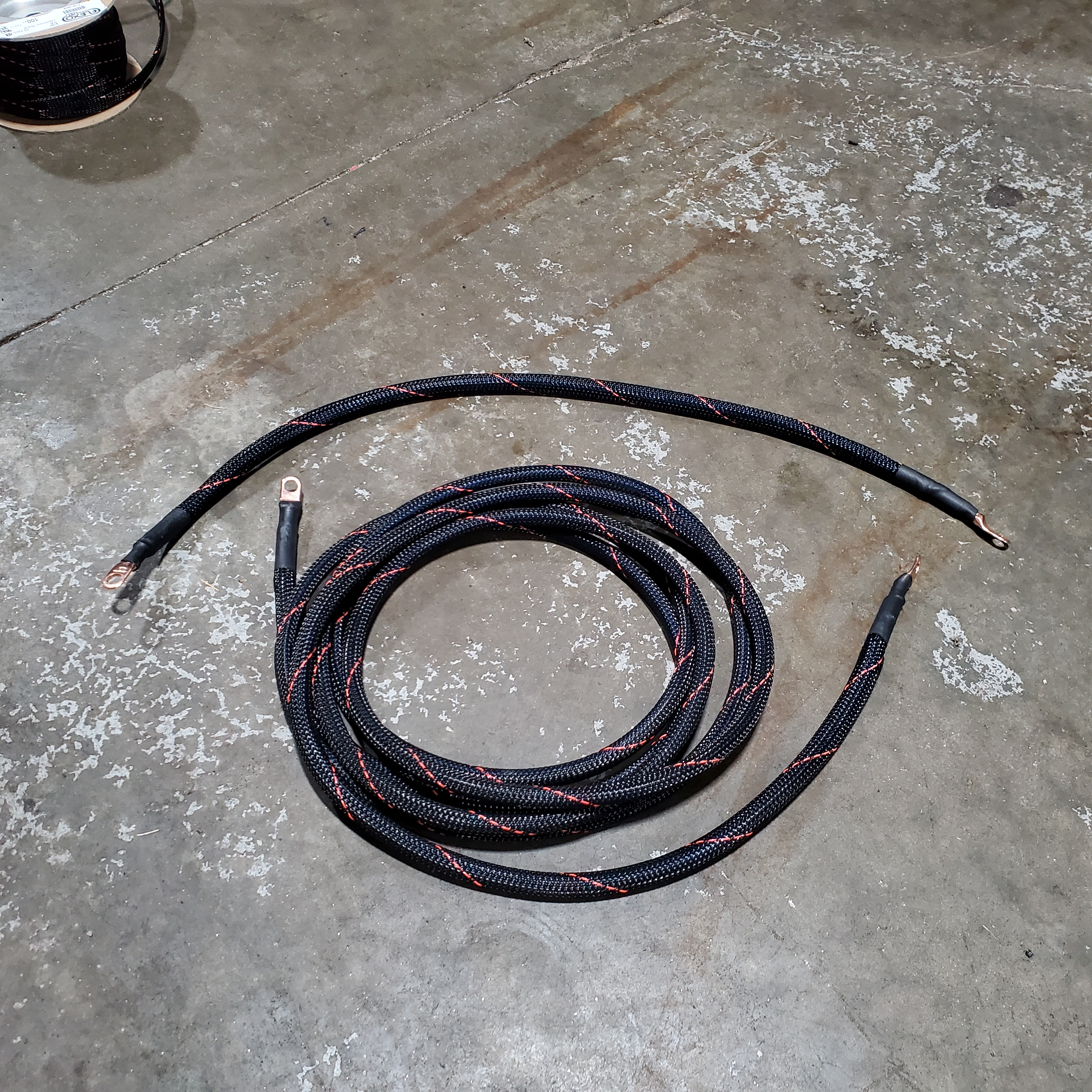
Before we begin installation, you will want to lay out your complete kit which should consist of the following:
- (3) 0gauge 12V power wires
- (2) 4gauge 12V power wires
- (1) 4gauge ground wires
- (1) Moroso battery quick disconnect
- (1) 200amp circuit breaker
- (1) 150amp circuit breaker
- (7) Self tap screws
- (1) Optional battery box
The kit laid out should look similar to the following pictures (some items not shown)

To begin you will start by removing the battery terminals (both factory terminals are 10mm) and then remove your battery.
You will then need to remove the factory battery tray as it is no longer needed.
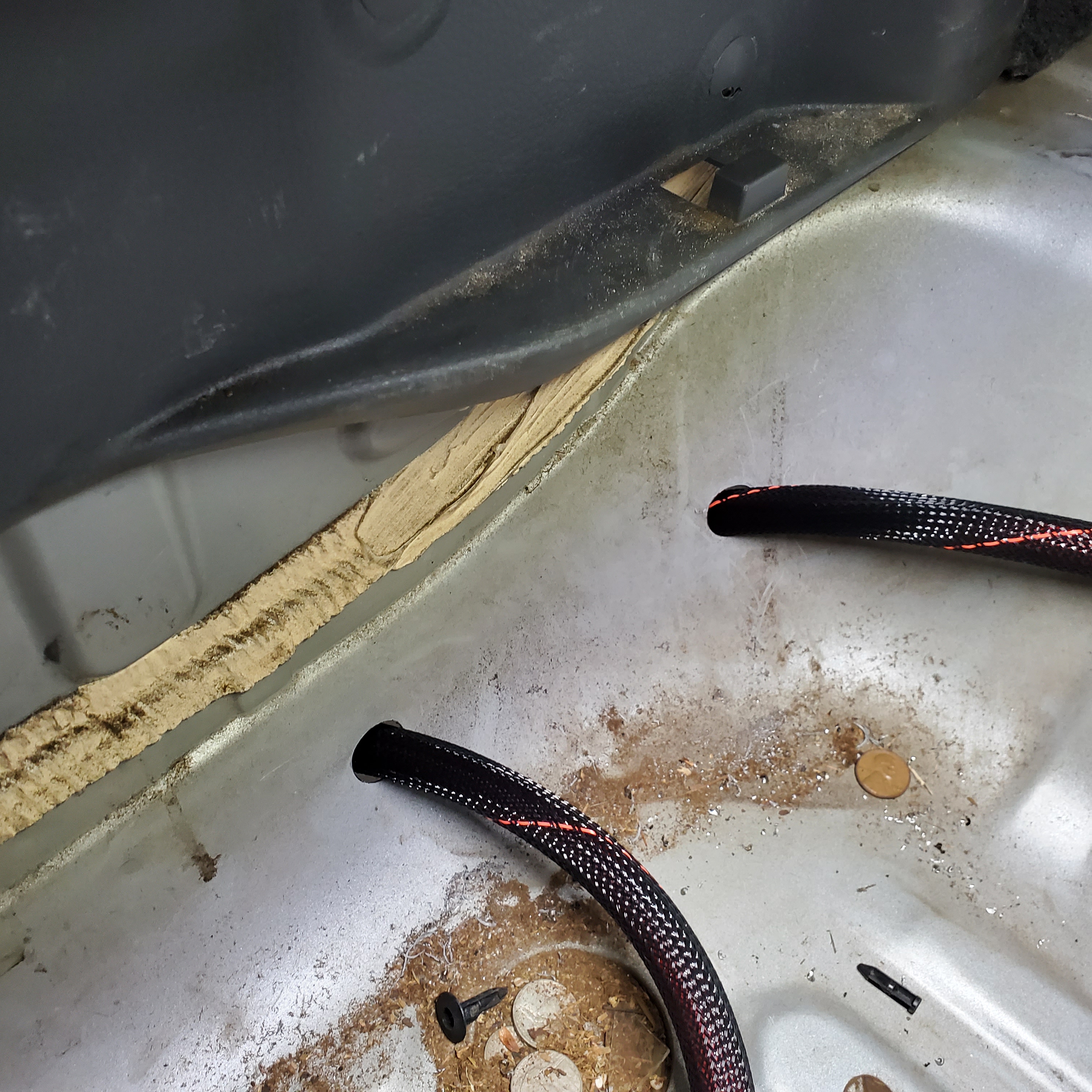
The next step is going to be moved to the rear trunk compartment. You will need to drill 2 holes in the rear of the trunk compartment spare tire well location like shown below. Make sure the 0 gauge wires can pass through with ease.
After you have confirmed fitment of the 0 gauge wires you will then need to drill the rear bumper to accommodate the Moroso quick-disconnect. When drilling the rear bumper, the best tool to use is a step style drill bit. Drill until the quick disconnect fits snug, do not go too far as it is not as easy to add material back to the bumper as it is to take it off.

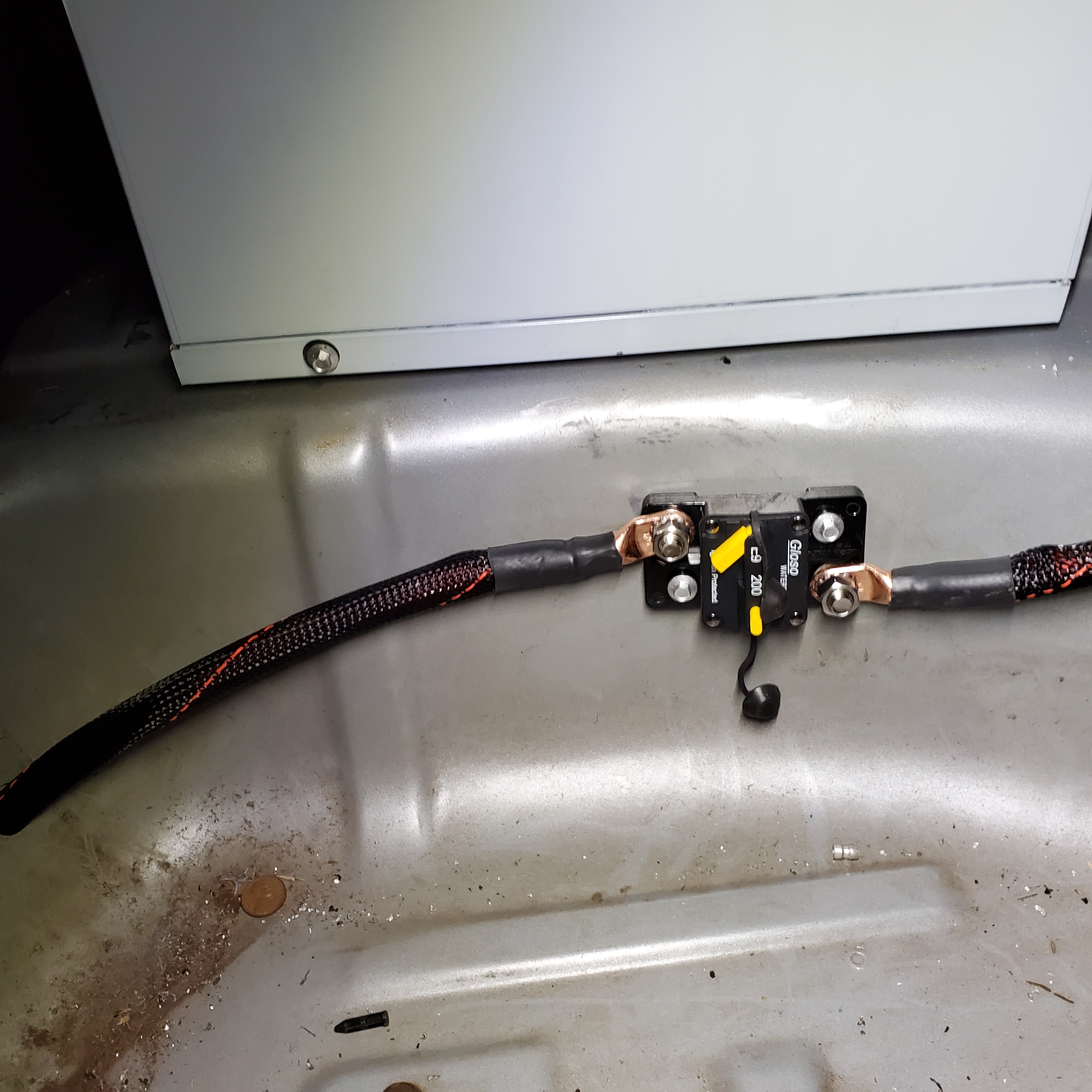
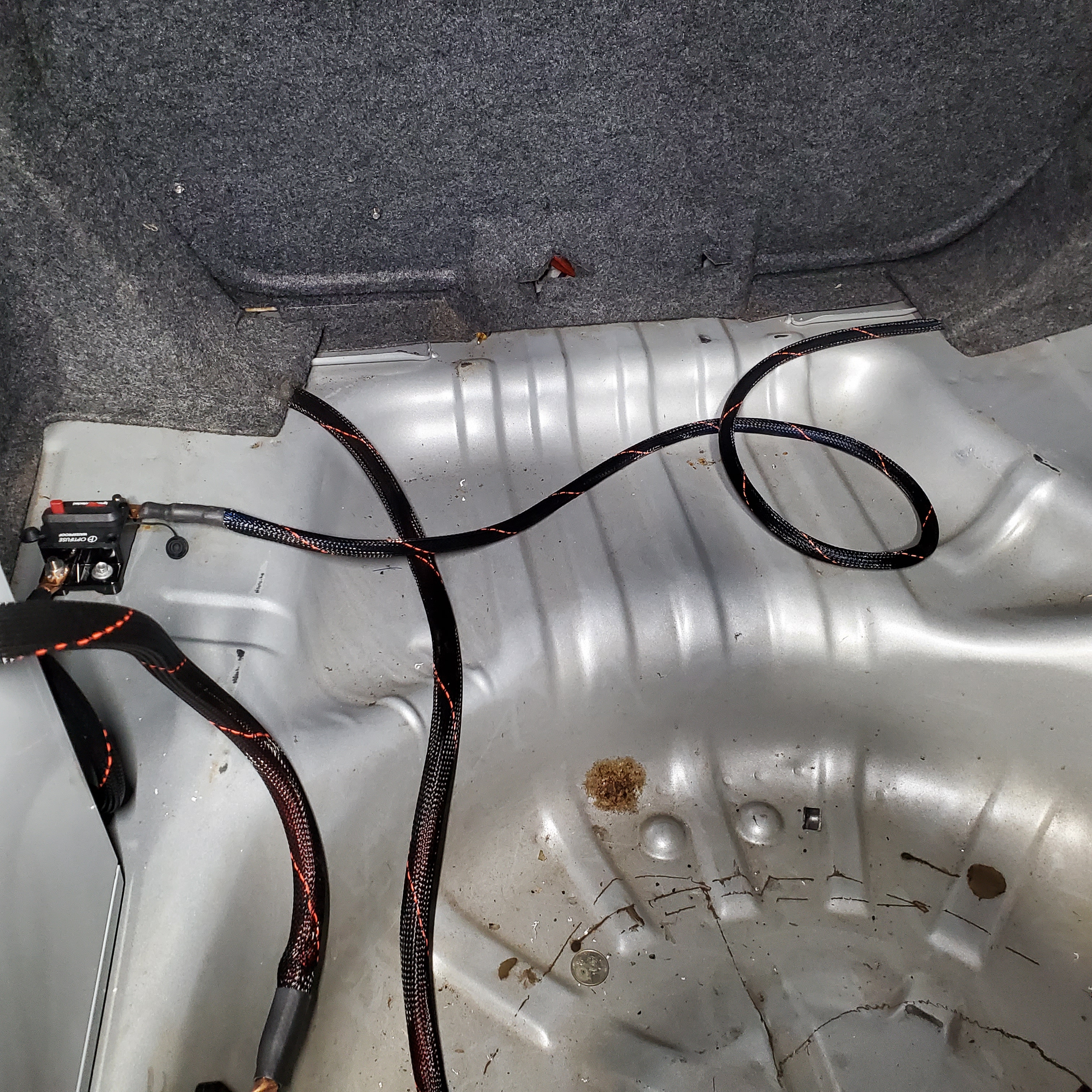
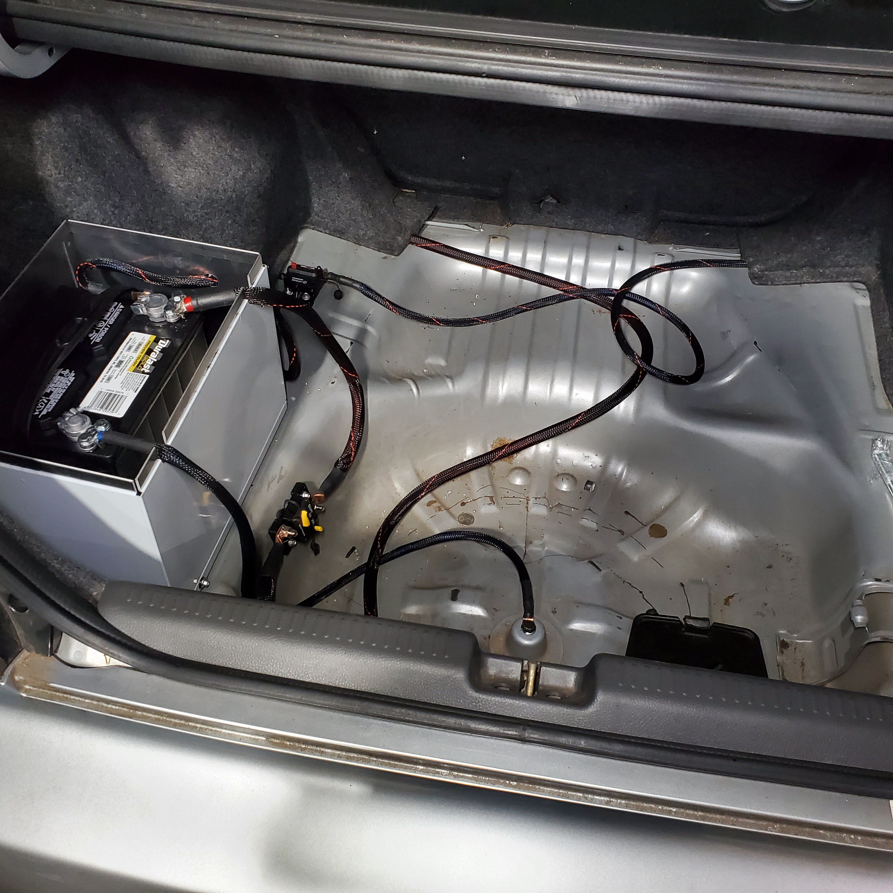
After this step has been taken and crash bar has been modified to accommodate the killswitch (if necessary) it is now time to mount your battery in its new location. We have chosen to use the rear left of the trunk compartment directly behind the taillight. Once you have your battery mounted it is now time to install the shorter 12V wire from the battery. Once the first 12V wire is set in place you will now need to select your desired location for the 200amp circuit breaker. Before mounting the circuit breaker, take the medium length 12V power wire and route it through the hole of the spare tire well that you have made and bolt it to the killswitch. With the short and medium length 12V power wires now installed you can finalize the mounting of your 200amp circuit breaker.
You can now route the 0gauge 12V power wire to the front of the engine compartment by passing through the trunk to the interior and routing along underneath all of the plastic sill panels. Make sure before routing into the interior you have secured this power wire to the other side of your Moroso killswitch. You will then need to remove the drivers side wheel and plastic wheel liner to gain access to the rubber wire grommet located in front of the drivers side door. Here you will need to poke a hole in the grommet large enough to pass through the 0gauge wire. Once the 0gauge wire has been passed through you can route it along the existing wiring at the top of the wheel well and secure with zip ties. Pass up the 0gauge power wire at an opening near the LF headlight assembly and route the wire to factory battery terminal. Once you have reached the factory battery terminal you will need to remove the existing power wire for the alternator so the alternator no longer receives power with all of the other accessories in order to allow the killswitch to do its job. You can now through bot the terminal of the 0gauge wire with the factory battery terminal and wrap electrical tape around it for added safety. Routing of the 12V power wire from trunk to the interior is shown below
Now it is time to set up the new power feed to your alternator. First you will start with the smaller 4gauge 12V power wire at the battery and route it to the 150amp circuit breaker that you can mount in front of the box (picture will be shown below on alternator power wire trunk routing). You will then take the longer 4gauge 12V power wire and route it from the 150amp circuit breaker and through the interior along the passenger side underneath the interior sill panels just like you did with the 0g 12V power wire. In order to get this 4gauge 12V power wire to the alternator you will need to now poke a hole in the rubber wire grommet on the firewall behind and below the intake manifold. At this time you must also now remove the factory power wire from the alternator. Once you have the new 4g 12V power wire routed through the rubber grommet at the firewall you can now bolt it to the alternator. From here you can finalize the mounting of your 150amp circuit breaker.
At this point you can now install your new battery ground wire. The ground wire will go directly from the battery terminal and bolt down to the spare tire holder location.
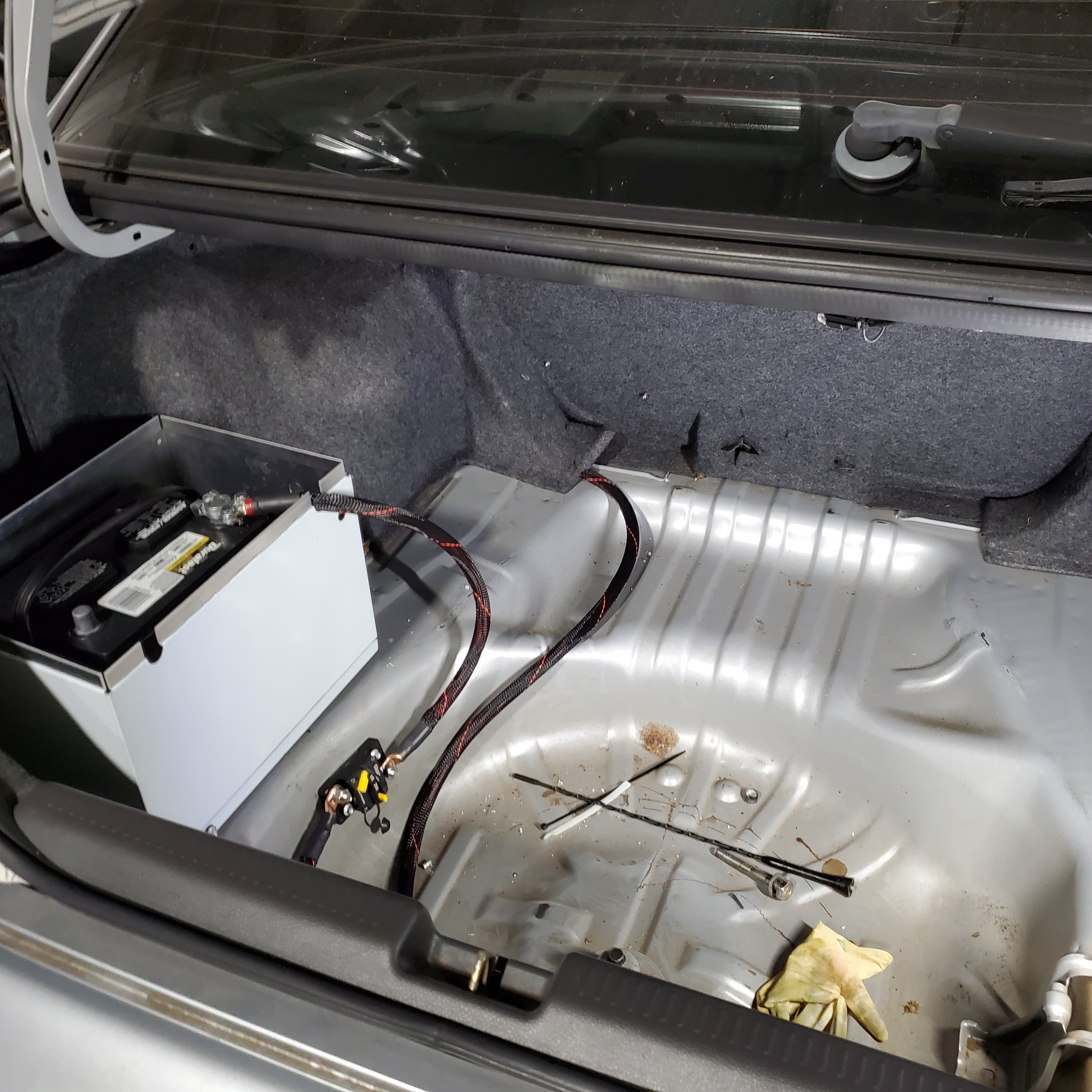
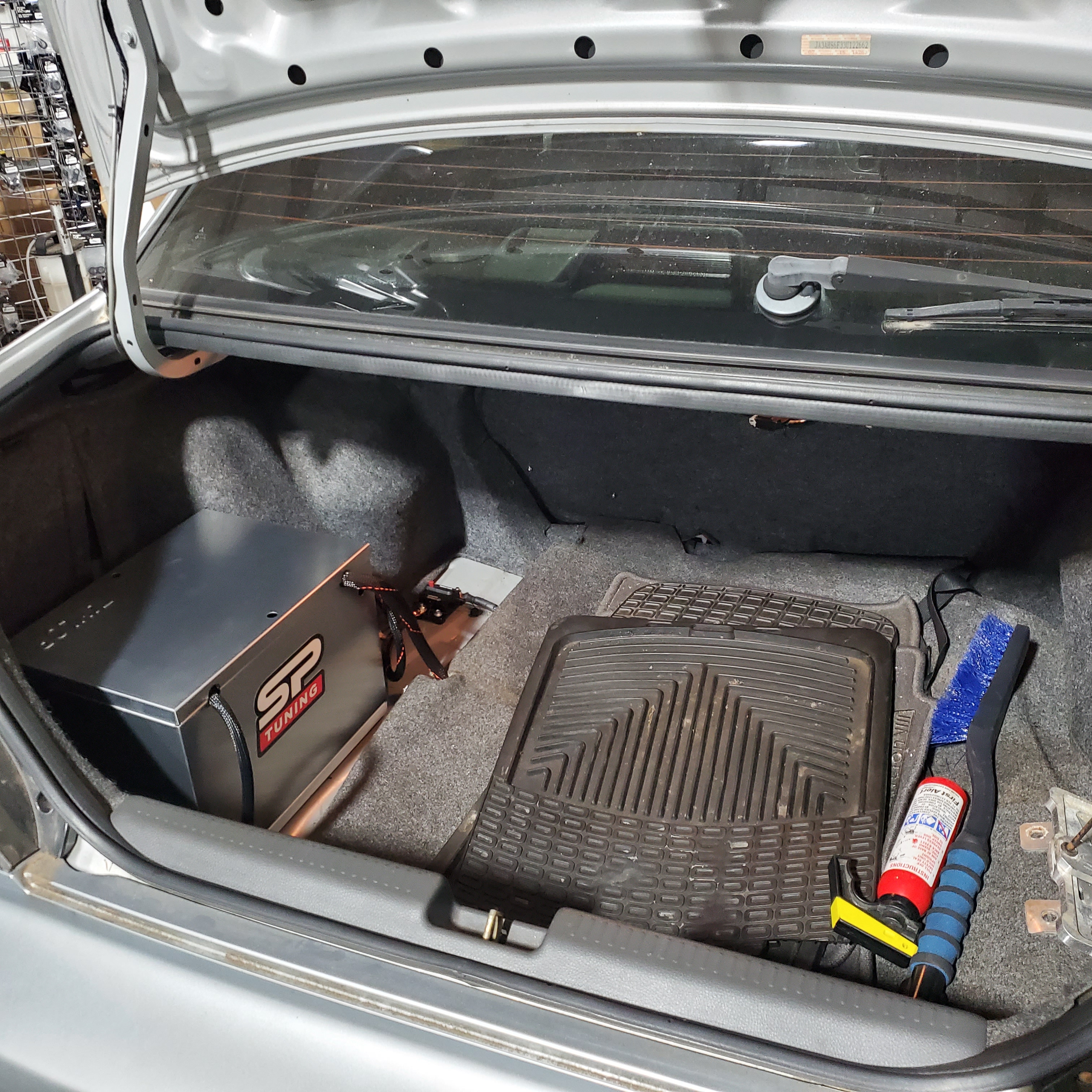
Now when you step back and look at your trunk it should look something like this:
In order to retain your trunk interior to appear as if not much has changed other than adding a battery you will need to modify the edging of the trunk carpet base to clear the battery and alternator circuit breaker as well as the battery box if you have one (of which you should if you are purchasing this kit to pass NHRA tech). At this point in time you can now turn the killswitch to the "ON" position and verify that you have power.
With the modified trunk carpet base your trunk compartment should look like this:
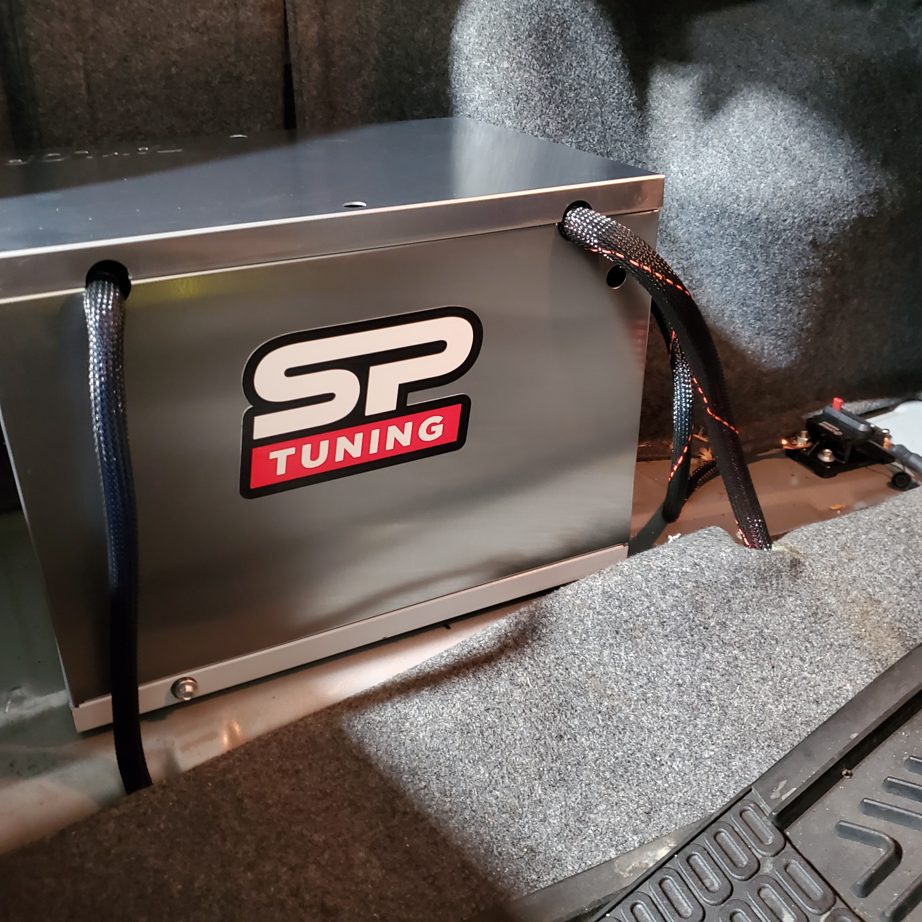
At this point you are ready to hit the track with your relocated battery setup on your Evo 7/8/9. Salp on your SP Tuning sticker to the side of your box and enjoy!
Any further questions please feel free to reach out using our website contact form.
Thanks! - Stephen @ SP Tuning LLC